Personal Project Review: AA Tester v3 (aka: Coulomb Counter Project)
Personal Project Review: AA Tester v3 (aka: Coulomb Counter Project)
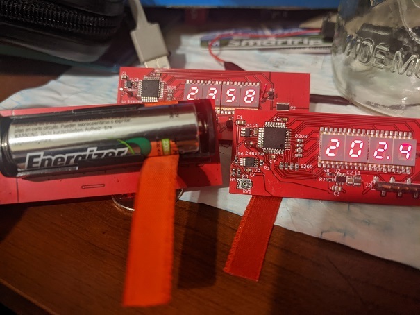
To get myself back into electronics, I pulled out an old project idea I've been wanting to do for a while, and that's a AA NiMH battery tester. I have a collection of ~30+ AA NiMHs that I use for various purposes: Flashlights, Switch Controller (yeah, they made an attachment), Electric Toothbrush, Walkie Talkies, etc. etc.
After a few years of abuse, these AA NiMHs degenerate, but at different rates! Even though I bought them all at roughly the same time, different levels of abuse made some cells barely hold a charge, while others work almost like new. How do I differentiate between them?
Simple: charge up the AA cells, then perform a current sensor / coulomb count against them. That is: measure the current out x time taken == total amp-hours that a particular AA cell can take. And if this value drifts too far away, I recognize it as a busted cell and send it to my local Home Depot for recycling.
First, I'll go over the schematic one-at-a-time for everyone.
V3? What's version1 or version 2?
Erm.... mistakes were made. Lets not talk about V1 or V2 right now...
7 Segment LED Driver
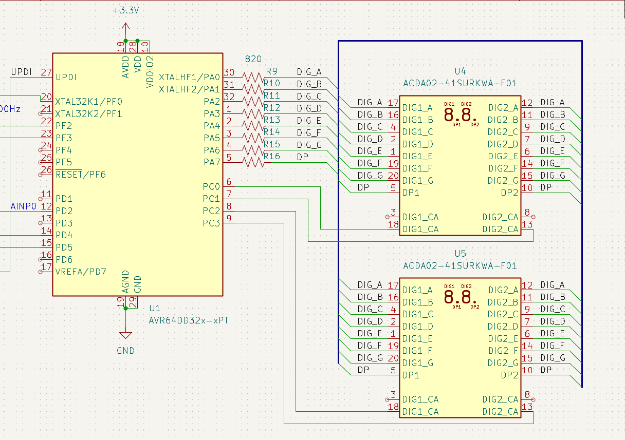
The "Digital" half is pretty simple, I take the surface-mount ACDA02-41SURKWA-F01 (https://www.digikey.com/en/products/detail/kingbright/ACDA02-41SURKWA-F01/3084667) 2-character 7-segment LED x2, and hook them up as appropriate to an AVR DD microcontroller.
At 3.3V Vcc and 1.6V Vforward LEDs, a 820 Ohm resistor will let ~1.8 mA of current, which testing has shown to be plenty bright enough for my purposes.
For the newer EEs out there, these devices are very dumb.
https://www.kingbrightusa.com/images/catalog/SPEC/ACDA02-41SURKWA-F01.pdf


These "Common Anode" LEDs have high-voltage all running from the same wire. So they only work with a little bit of microcontroller magic: I turn on one-digit at a time (ex: Digit#1 goes to high-voltage, then I can display a 0 with the binary output "11000000" (low-voltage on segment abcdef, and high-voltage on segment g).
I then turn Digit#1 off (set voltage to low), and then set Digit#2 to high, and display the same ports "10011111", which will display the "1" character.
Etc. etc. I can cycle through Digit1, 2, 3 and 4 a thousand-times per second so that the human eye cannot see them changing so quickly. This ultimately displays a 4-digit number.
Battery, Current Sense, and Instrumentation Amplifier

The battery is just that: a single AA-battery holder. The entirety of this circuit runs through the 0.1 Ohm current sense resistor, meaning even the power behind the microcontroller/LEDs gets "counted".
For beginners out there: an OpAmp is an "analog computer", allowing electrical engineers to add, subtract, multiply, divide, differentiate, or integrate voltages.
An Instrumentation OpAmp is a specialized OpAmp that focuses upon differential signals and multiplication with a constant (aka: C * (A - B) type calculations, where C is a constant). In particular, Instrumentation Amplifiers increase the accuracy of the (A - B) calculation by maximizing the CMRR (common mode rejection ratio), aka the "minimization of error from changing voltages", and PSRR (Power Supply rejection ratio), aka the "minimization of error from changing power-supply".
As a tradeoff, Instrumentation OpAmps have worse bandwidth and less flexibility.
A Zero-Drift Amplifer is a further specialization that focuses upon very low offset voltages (aka: the where the OpAmp thinks 0-voltage is located in reality).
Nominally, you could use a general-purpose OpAmp, but its always best to pick the specialized amplifier for any particular job. As such: I picked the MCP6N16-10 is a Zero Drift AND Instrumentation amplifier. Because its zero-drift, it has 20uV specified offset voltage (or 0V will be somewhere around +/- 0.00002V in reality). There's a further requirement that the MCP6N16-10 only works if I set the gain (aka: the "C" in C * (A-B) calculation) at 10x or higher.
In this case, I set the gain at 27.3.
Now lets step through what happens here: When say 500mAmps rushes through the current-sense resistor

V = I * R
Thus, the 500mA * 0.1 == 0.05V change across R1. MCP6N16-10 very accurately performs (R1_high - R1_low) calculation (thanks to very low offset voltage), and thanks to the 27.3x multiplier, will output 1.365V.
I then added a 100k / 10uF simple low-pass filter for anti-aliasing as well as averaging out in the analog domain. This effectively creates a moving average of the most recent ~6.28 seconds. (Or perhaps, I have a low pass filter with Fc of 0.16Hz if you want to think about it in the frequency domain).
After all that, it goes into my Microcontroller. I've configured the AVR DD to have a 2.048Vref for the ADC. Alternatively, you can think of the 27.3x multiplier + 0.1 Ohm resistor + 2.048V Vref and 12-bit ADC to reasonably accurately measure resolutions of ~180 microamps per least-significant bit, across ~0mA through 750mA or so worth of nominal range.
All resistors are +/- 1%, though the Vref of the microcontroller is +/-4%.
The load

A very simple low-side NMOS switch driven by the AVR DD. More on this later, I think I made an error with this version that I'm fixing in my next design. But the uC simply drives the NMOS high to let the 2.2Ohm resistor send ~500+ mA across the battery.
The 3.3V Boost Converter

Various parts on this board require more voltage. The whole board is powered by only a single AA cell, which will vary between 0.9V to 1.4V depending on how charged the AA cell is.
The boost converter takes this voltage / current / power, and converts it into 3.3V. The design here is simply following the MCP1640BCH data-sheet, and then picking new resistors that were found elsewhere on my board (instead of the original resistors that were in the docs).
KiCAD Notes
KiCAD is a free CAD tool to help create PCBs.
-
Create and/or Select Symbols -- These represent the various chips and parts you'll put into your design.
-
Create a Schematic -- KiCAD will use the schematic to automatically check which parts need to be connected to each other.
-
Create and/or Select Footprints -- Each symbol is then given a footprint, the 2D representation of how it will look like on a PCB.
-
Layout PCB -- First configure the PCB to have the settings of your manufacturer. click "Update from Schematic" to import data from step #2 and #3, and then just arrange the items in the PCB editor till things look good.

The PCB Manufacturer
I wanted to try out DKRed this time. https://www.digikey.com/en/resources/dkred
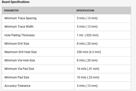
I chose the 2-layer PCB settings and configured KiCAD with the board specifications.
The PCB Design

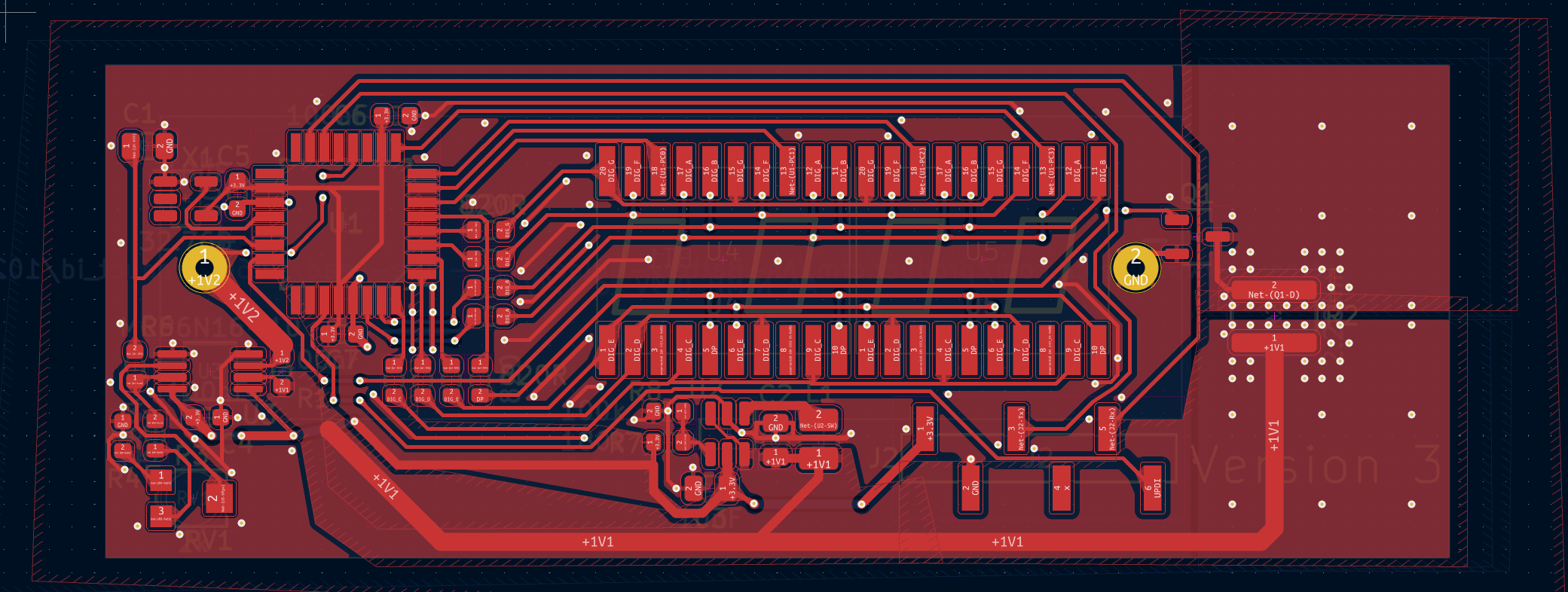
It is impossible to have a solid ground-plane on a 2-layer board, but I made the ground plane as solid as I possibly could.
Of note is the PCB-heatsink on the right side of the board, as well as the "sideways resistor". Let me bring attention to the 2.2 Ohm resistor really quick.
https://www.digikey.com/en/products/detail/vishay-dale/RCL12182R20JNEK/2556524
This resistor is designed with "sideways" leads so that the heat would more easily transfer into a "PCB Heatsink". All a PCB Heatsink is is a large section of copper you leave for non-electrical reasons... but just for the heat-sinking reasons alone.
The Mistake: Bad EMI???
Did you catch the mistake? In my haste to maximize the PCB Heatsink size, I've removed the ground-plane from under the 2.2 Ohm resistor.
Now... maybe in isolation that's not a big deal. Except upon finding and testing this design, I've found that the rise-time of that NMOS is 20 nanoseconds in practice.
And when the voltage reaches near the 0.95V cutoff mark, the code will purposefully PWM to try to train the last bits of the AA cell down to the 0.95V cutoff. (When a cell is 0.94V, it cuts off the NMOS, but this immediately causes the voltage to increase back to about 1.02V, causing the code to turn the NMOS back on... causing the voltage to drop to 0.94V, etc. etc. at a rapid rate).
I'm fairly certain that I've got bad EMI noise in the 50MHz+ range in practice, though I don't really have a means to test it. My next version will be a 4-layer board with better respect for grounding issues.
As it turns out, a significant amount of the traces going to the 7-seg LEDs use a good amount of room (and also cut up the ground plane on the 2nd layer). So I think a 4-layer board will shave off a few more millimeters off the width of this design.
My next version includes a "slow start" capacitor on the NMOS, to have microseconds of risetime on the NMOS rather than the 20ns of risetime in this prototype. Also, with a 4 layer board, I should (theoretically) minimize any EMI issue that would come about (not that I really have a good measurement tool for that).
Prototyping and Assembly

I applied low-melt lead-free solder paste, manually placed all the parts with a tweezer. For those who have never used solder-paste, its pretty easy. Solder paste is sticky enough that the parts remain in the proper place after you stick them on. I did buy a solder paste stencil (~$10 these days) to make the application of solder paste braindead easy on my 3x prototypes.
I used the "Electric Skillet" method (turn on the skillet until the solder paste melts, turn off the skillet, then use hot-air rework station to fix any tombstones). Thanks to the magic of solder and surface tension, the solder itself will mostly pull themselves into the correct spots when the solder is molten. So you don't need to be very precise with your placement.
I used a x10 Loupe to inspect for solder bridges. Solder bridges were fixed with a soldering iron + solder wick. Once the surface-mount parts were all confirmed to be good, I added the AA-holder to the back and used traditional leaded-solder to attach the pin through the though-hole... erm... holes.
I'm fairly certain that I messed up the fragile oscillators due to neglect. My clocks are severely off, by 5% or so (the clock is supposed to be 20ppm, or 0.002% accurate, so 5% is severely off). So next time, I'll be more careful about my soldering procedure.
Programming
Microchip Studio is pretty straightforward, and I don't think the code is very difficult. I manually initialized the various hardware bits of the AVR DD by reading the manual.

Initialization routines have a recipe from the manual to follow and the documentation is rather straightforward. I did come across a bug with "AC_MUXNEG_DACREF_gc" being the wrong value (shame Microchip!! You messed up your .h files!!), but it wasn't too difficult to see the error when the code ran and I fixed it up in a few minutes. (manually used the value from the manual: 4).
Code is written in polling style, there's no OS here so I just have an infinite loop that's checking for the clock to change and reacting to the clock.
4096x per second, I update which digit I'm displaying.
1024x per second, I cycle through all 4 digits. I use 16-bit BCD so that I only need to bitshift + AND to extract the values in this most common operation.
64x per second I check the Analog Comparator for if the battery has dropped below 0.95V. If so, I turn off PortF (the NMOS).
16x per second I update the milliamp BCD number to display later. I have a very expensive division / modulus operation here, but the AVR DD even at 4MHz is fast enough to perform this operation without causing issues in practice. I also have a moving-average queue to average out the last 16 values (ie: 1 second), to help cut down on noise in the display.
2x per second I update the AmpHr number. AmpHr is a 64-bit fixed-point (32-bit above 1.0, and 32-bits for the fractional half).
1x per second I swap between AmpHr display and miliamp display.
The ADC updates as quickly as possible asynchronously. There are no interrupts, I simply read from the ADC regularly and add the ADC value to the 1/64th miliamp variables (which will be divided out / normalized later).
The code is only 250 lines long with substantial amounts of comments. I don't use interrupts, I simply poll with if() statements on all the above conditions. Everything completes fast enough ("realtime enough") that all the code just works without any of the complex features available to me.
Calibration
I pulled out my benchtop Fluke 45 to calibrate the ADC errors with a #define. This is an old benchtop multimeter with ~5 digits of display, giving me accuracy to 0.0001Amps of measurement. (Alas: the more accurate measurement of 100.00 mAmps only works at 100mA and less, and my design is 500mA).
I've noticed a decent amount of non-linearity. I wonder if I'm leaking current somewhere? Or maybe there's more offset error due to something unknown? Still, the overall error is within 1% across the range, and maybe I could calibrate both a zero and the 500mA points to help minimize this non-linearity.
Calibration is just me changing a #define in the C code. Nominally I have a 2k trimmer pot here, but it seems like #defines to trim away the error was sufficient in practice. Next version won't have the trimmer pot.
Questions?
Lemme know if anything doesn't make sense to yall. I don't think this is an especially difficult project. I hope I gave enough details so that the newer EEs in this community could follow along.
Feel free to ping me for questions. I know someone out there was looking for a current-sensor project. This is my current sensor project, probably different than what you are going to build, but maybe its a source of inspiration for you.
You're viewing a single thread.
Very cool! This is the kind of stuff i want to see. Is AVR still the best choice for this? Any Risc-V ICs that can fill this type of role yet?
This kind of project doesn't care about the core at all. This is almost 100% about the quality of the ADC you get.
AVR EA is what I went with Version4. But today, Microchip has begun to release AVR EB, which is a few cents cheaper than the EA (but the EB only has 3kB of RAM, while the EA only has 6kB). But there's very little processor/RAM usage here, the code is less than 300 lines and I'm only using a couple dozen bytes of RAM actually...
AVR EA and AVR EB have 16x gain and 12-bit differential ADCs with 1024x oversampling. See the Version4 design below, where I can hook up the EA or EB's advanced ADC to a simple current sense resistor (plus a RC low-pass filter for antialiasing)
AVR also supports like 200mA of push/pull current, so the 7-seg LEDs can be pushed by a singular GPIO pin directly. See PC0 / PC1 / PC2 / PC3, a number of lower-current microcontrollers could fail with the 7-seg LED design I used here (~2mA nominal per segment x 8 worst-case segments == 16mA worst-case. Which is beyond the specs of something as common as the RP2040 actually). 40mA push/pull per pin and 200mA overall is useful for pushing current to LEDs like this design, but 16mA is possible for many chips (but not all of the common chips).
AVR DD was used for Version 3, but its not the primary component of this project. The "star" of Version3 is the MCP6N16 Instrumentation Amplifier, which provides a highly accurate voltage-multiplier onto the sense-resistor and converts the differential signal into a form that most microcontrollers could do. I was playing around with an instrumentation-amp for various reasons for V3, but its not the best analog design IMO. (I should have gone with a simpler current-sense amplifier), but there's benefits to doing "learning projects" and playing around with general purpose chips like the MCP6N16.
I wouldn't necessarily say that "AVR is the best", but its what I know and the specs are sufficient.
Any Risc-V ICs that can fill this type of role yet?
The core really isn't important for these kinds of projects. Look at the I/O, the power, the current you can push/pull, the ADCs, the quality of the timers, etc. etc.