This argument would outlaw a USB flash drive, "Your Honor, this device can store the contents of this 30 old game, it needs to be outlawed to protect all intellectual property"
Sounds like Scientology
Alliexpress search is weird. It tends to focus on similar items you've viewed, so once you find a product you get better searches related to that product for a short while.
Looks like you can find replacements on Alliexpress. https://www.aliexpress.us/item/3256805584512736.html
And why the Franklin Ace 1200 lost in court to Apple, copied Roms.
Full reverse engineering, using any plans or leaks from Sony would put them in legal trouble.
So for this job I used:
- Head Visor for Magnification
- Quick 957DW+ Hot Air Station
- Hakko FX-888D Soldering Iron
- Solder and Flux
You can definitely do this type of work with a cheaper iron like a Pinecil or KSGER T12 of alliexpress.
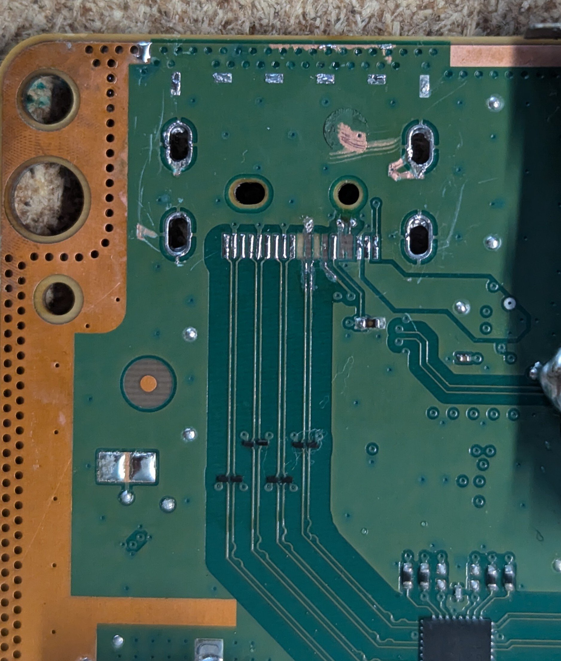
Some background, I originally removed the chips from the board on the left for a Pocket Color Build. It's original fault was no power, which turned out to be a dirty power switch and corroded battery contacts.
The new board had signs of corrosion under the solder mask and previous work (bent ram pins and bridges on the cpu). I decided to move the chips on the other instead of trying to restore the traces. Soldering all went well, until my hand slipped while testing if the connections were solid. One of the pins (bottom left) is pretty bent and the pad on the end was partially lifted.
I was able to heat all those back up and confirm no bridges and the pads are connected. Booted up a quick game to test a screen, sounds and all the buttons. Everything is working.
Moral of the story, be careful and don't put too much pressure on those pins.
Hot air station. Put down some tacky flux and kept it moving around the chips at about 380c.
Thanks! I've built a MGBC, a DMGC, a Funny playing GBA so I have some experience (though very much still an amateur).
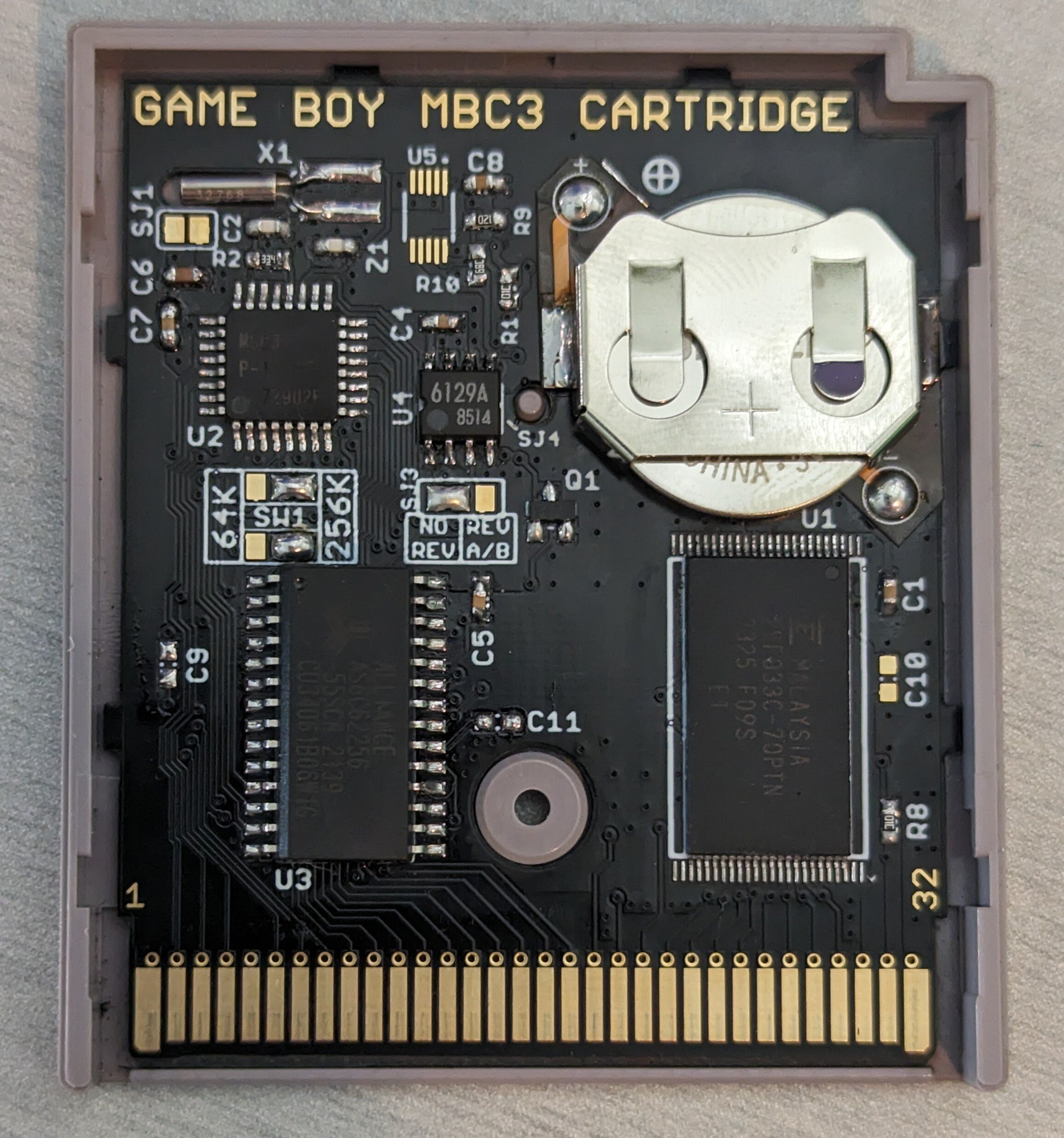
Thanks! Getting them off was probably harder than soldering them on. It took quite a bit of heat to melt the existing solder. After that, line up the pins and tac it in place and use drag soldering with plenty of flux.
The SGB CPU is compatible with the DMG. By swapping the CPU, your Gameboy will skip the falling Nintendo animation. This decreases the boot speed.
Do you want to celebrate the best games on the planet? Pull up a console and get playing for National Video Game Day 2018 on September 12!

What's everyone playing? I'm enjoying Mr. Driller for the GBC.
This is an open source project that adds a GBC processor and screen into a DMG shell. Have to say, I really enjoy the weight. The github can be found here [https://github.com/MouseBiteLabs/Game-Boy-DMG-Color].
Thought I would show this off here too.
I think the laws need to clarify the difference between just hosting vs suggesting content. Tik Tok should be responsible since it suggested the dangerous video, unlike if it was just hosted on an AWS server.
This was my first attempt doing a trace repair on a HDMI port. Seems like everything seems to be working after replacing those caps as well. Played through the tutorial of gears 5 with no issues.
What I've tested:
- Playing downloaded game
- Playing a Blu-ray
- Playing on a 4k TV and 1440 monitor. This one the auto detect preferred 120hz 1080p but manually selecting resolution works great.
What I've learned:
- Wired all the pads before soldering the port. I attached the front wires after the port was soldered. Should have just done them all.
- A cheap grinding pen is so much easier to use than a knife to expose the traces.
- 0201 are very hard to work with.
Yeah that makes sense, Microsoft is definitely going to keep costs down and not switch out those reels. Based on the other info, these are 22uf 20%, so in spec with the others I've measured.
Luckily all the c17x are 0603 22uf, 20% caps. Thanks for pointing me to the image so I could compare it to the schematics. Now I have to go through and look for others. No idea how this could have even happened.
Good eye, I need to go over the entire board again and look for those. Combined with the other answer that help me with a revision that actually is labeled, you are right. It should be a 22uf 6.3 0603 decoupling cap.
Picked up this Series X to do a trace repair for the hdmi, turns out 2 caps were ripped off the board as well. The one was still partially connected and easy to bodge. The second circled is missing. I'm curious if anyone knows the replacement value.
The similar caps in the area all read between 18.6 to 19.6 uf when out of circuit, so it could be a few values (though no guarantee this cap wasn't unique and completely different).
No, for that you still need a real broadband adapter.
Yeah the dev will. He always releases cores publicly when they are out of beta.
I happen to have a board from my FunnyPlaying build so I figured I'd give it a shot. Used enamel wire to make the button contacts and got 3.3v from the cart slot. I also removed the caps as to not power any circuits that didn't need (CPU and RAM were donors to the other board). Power is provided via AA batteries.
Still very much a work in progress but it works reasonably well (about 8ms of lag). I want to ultimately create an easier to install PCB rather than the perfboard I used.
Contribute to v1605/SNES-BLE development by creating an account on GitHub.
An update to my previous post. I was able to improive the average lag by disabling the serial monitor, passing a reference of the controller to the polling logic (eliminating the need to loop over the current state and previous state to determine if buttons should be pressed), and adding a 1ms delay between loops (should have realized that the board need some down time between calls). I've added the code since I think 8ms is a perfectly good lag result for a diy project.
Took a badly marginal gba pcb and transplanted the CPU and RAM into this new motherboard. The soldering was a nice challenge but I had an issue with the cart slot. A pin was bent, so had to fix that before games would boot. Very happy with the result. I've uploaded a picture of the back of the shell as well. https://imgur.com/a/opXFA5B
Also in person, the plastic is not cloudy at all. The motherboard is here https://funnyplaying.com/products/gba-custom-upgraded-motherboard-replacement?variant=40990162059325
cross-posted from: https://lemmy.world/post/13199828
> Printed using hatchbox wood pla. I had a few issues with standoffs but a little glue fix those right up. I'm very happy with the way it turned out. Just waiting on the release of flippy drive to call it complete. > > Links to all the models I used: > > https://www.thingiverse.com/tessa-wolf/designs > https://www.printables.com/model/469283-gamecube-jewel > https://www.printables.com/model/117561-gamecube-power-button > https://www.printables.com/model/280005-gamecube-reset-button > https://www.thingiverse.com/thing:2644517
Printed using hatchbox wood pla. I had a few issues with standoffs but a little glue fix those right up. I'm very happy with the way it turned out. Just waiting on the release of flippy drive to call it complete.
Links to all the models I used:
https://www.thingiverse.com/tessa-wolf/designs https://www.printables.com/model/469283-gamecube-jewel https://www.printables.com/model/117561-gamecube-power-button https://www.printables.com/model/280005-gamecube-reset-button https://www.thingiverse.com/thing:2644517
This was my attempt to create a a SNES to Bluetooth adapter. It works but the average latency was 18.35ms, which I think is too much to be considered a good controller.
This unit was just sold as a parts board. I bought it to use as a donor board but figured I could get it working first (this screen was from a different unit). Turns out someone had opened the power switch to clean it, but somehow a solder blob made it into the switch. That was jamming the power switch. Still a donor board through, the volume slider is pretty rusty.
Contribute to v1605/retrotink-4k-automation development by creating an account on GitHub.

cross-posted from: https://lemmy.world/post/11912700
> I added some documentation on how I'm automating remote control inputs on the 4k. Examples include a template for an IR transmitter, a python script to parse profile information off the SD card for use in automation, and an example of selecting a custom profile based on its name. Hopefully it can be useful, if only just to give some interesting node-red examples.
Contribute to v1605/retrotink-4k-automation development by creating an account on GitHub.
I added some documentation on how I'm automating remote control inputs on the 4k. Examples include a template for an IR transmitter, a python script to parse profile information off the SD card for use in automation, and an example of selecting a custom profile based on its name. Hopefully it can be useful, if only just to give some interesting node-red examples.
My hand slipped while disassembling the system (original goal was to replace shoulder buttons and plastic housing). I had to scrape away points on the board and use some 32 awg enameled wire to recreate the connections. Good news is every fits and is back in working order.
A wifi pico w remote for the gbs-control. Contribute to v1605/gbs-remote development by creating an account on GitHub.
I've made the improvements I listed in my previous post. The GitHub link contains a link to the LCD I used in the project and basic instructions.