
Soldering
- Any Part Is Surface Mount If You Are Brave Enoughimgur.com Siemens - Sipart actuator controler
Discover the magic of the internet at Imgur, a community powered entertainment destination. Lift your spirits with funny jokes, trending memes, entertaining gifs, inspiring stories, viral videos, and so much more from users like nik282000.
I made this 'fix' about 7 years ago and the device is still in use today. I know which one it is because my 5ohm resistor came out around 4.9 so the device always runs 2% out of spec.
- Corroded screen cable fix.
Yes, it worked perfectly! The repaired broken line was apparently power to the LED backlight.
- First Time Using A Stencil (Summercart 64)
This was the first time I've used a stencil and solder paste to build up a pcb. It was so much easier to get all the components aligned and soldered on the board (on the back, there are 38 0603 capacitors which are always time consuming to hand solder). After just had to clear a few bridges and added a little extra solder to U1.
- Frankenduino!
I'm working on replacing the Schneider SmartRelay on an Atlas Vista 613 wheelchair lift that I bought for my dad. The Atlas technician agrees that the SmartRelay is probably shot and the replacement is $1,000 wholesale. I built a replacement using an Arduino Nano, a UNL2803A Darlington array, a switching 7805, a bunch of Zener diodes, and a handfull of Schneider industrial relays.
Unfortunately, I let the smoke out of my very last Nano and needed to keep the project moving. So...I took a small piece of protoboard, an Arduino ProMini 168, and some jumper wire and created this Frankenduino. It's the same pinout as the Nano with none of the nice supporting stuff like an ICP port, USB, voltage regulators, etc. It will keep the development moving while I'm waiting for the 10 Nanos I have on order to arrive.
- SMD Cartridge
With maple syrup season fast approaching (4 months ish) my thoughts have turned to working on the Sapmaster once again. I'm going to design and build a new top and bottom board this year to fit in the BUD DMB-4774 DIN case that I use for the SapMaster controller. That's going to involve a bunch of SMD soldering which reminded me of the irritation that soldering with loose pieces of SMD tape causes me.
To that end, I went looking for an SMD dispenser cartridge that would meet my needs. I couldn't find one so I decided to design my own.
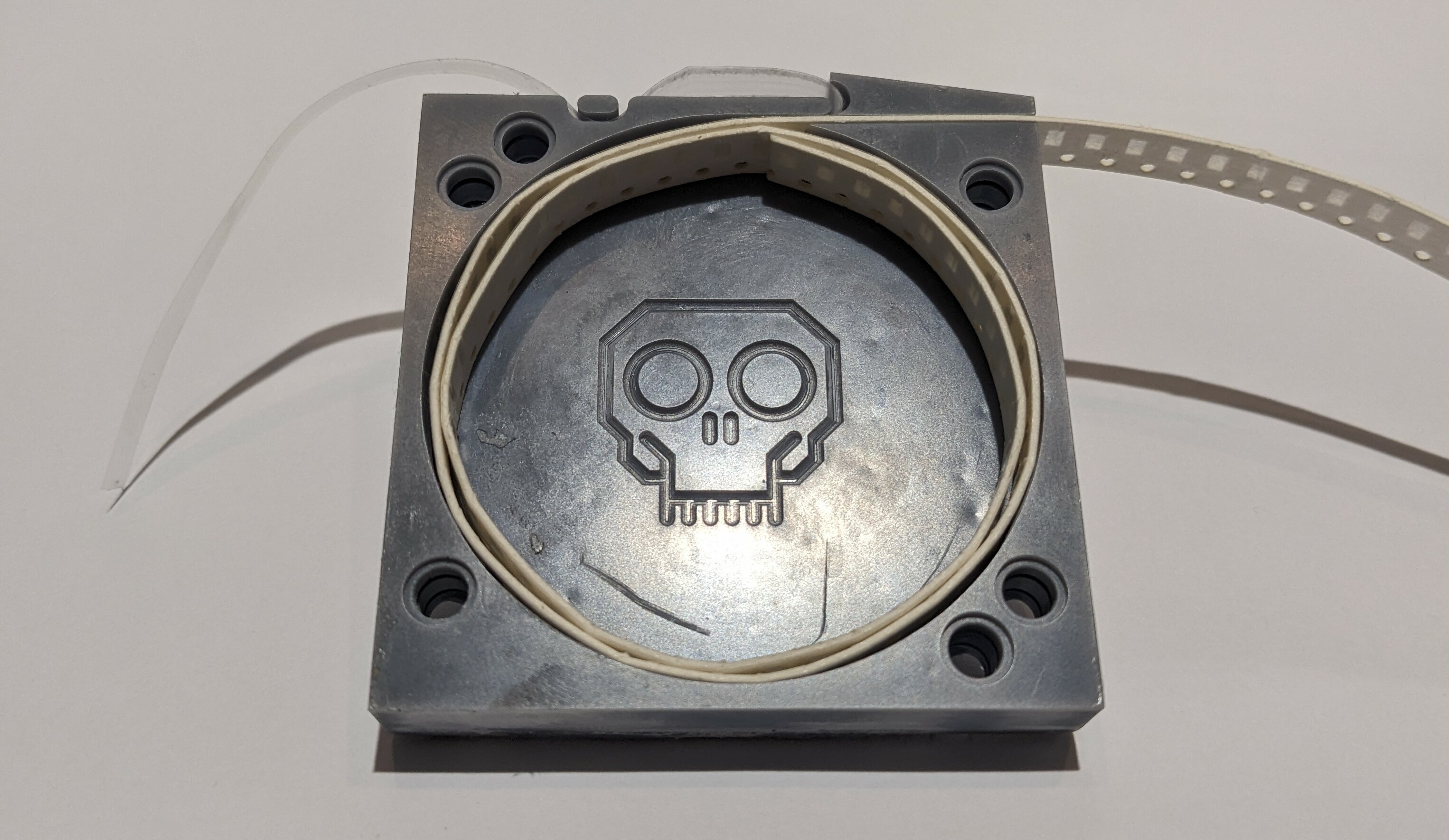
This is version 4.1 of the design. It holds around 5 feet of standard 8mm paper tape which is around 1,000 components. The tape comes out the straight slot at the upper right. The clear cover tape goes out the curved slot and can be hooked under the little pin upper left. The point of the splitter between the straight and curved slots holds the components in place so they don't fall out before you pull the tape out of the slot.
I will generally use single cartridges with a cover but the friends I work with say that they want them to connect together. I considered a number of options but they all involved pins and holes or tabs and slots and I wanted the individual covered cartridges to be nice and clean. What I settled on are the holes you see around the corners of this cartridge. The accept a standard LEGO Technics connecting pin and allow you to gang together any number of cartridges.
I'm all setup to make versions for different widths and thicknesses of tape as well. The cover has four LEGO Technics like pins to plug into the holes in the cartridge.
I expect to start printing some to actually use in a few days when the magnetic base plate for my 3D printer arrives.
- Beginner Problems - Flux Management
I've posted a few videos now of myself soldering header strips and some SMDs with my good quality soldering tools and with an inexpensive soldering iron that I bought at Walmart. I sent a link to the friends, the hardware designed and programmer, who I often work with. One designs the boards, the other programs them. I do some of their fine soldering work for them.
They were amused by the Walmart soldering iron videos and remarked that they were surprised that soldering QFPs was even possible with that iron.
That got us to talking and me to thinking. What is the difference between the tools and materials and the technique used by someone who makes it look easy and the tools and materials and the technique used by beginners who struggle?
I would like to propose that the biggest issue that beginners have is flux management.
Electronic solder isn't a solid metal wire. The solder we use for electronics most often includes flux. The flux is included in one or more cores inside the solder wire.
Multicore solder, which I use, even has these cores in their logo.
Here is the Multicore solder I have sitting on my desk.
I believe that many of the problems beginners run into involve not understanding the role of flux or how short lived it is. If you apply solder to your soldering iron the flux is gone in a second or two. The solder will them oxidize and refuse to stick to anything. Effective soldering, soldering that looks easy, involves getting the heat into the parts, applying the right amount of solder quickly and smoothly, then removing the heat before the flux has burned off. This is my going back and touching up your joints causes so many problems. The solder is dry (no flux) and oxidized and doesn't cooperate.
If you've watched my SOIC-8 or QFP-32 soldering videos you will see that I apply liquid flux. This is because I apply the solder to my soldering iron then drag solder the pins. The flux has all burned off of the solder and it will not stick to the pins without the liquid flux. I also used liquid flux in the Fixing Bad Solder video.
So...I believe that a good understanding of the role and short lifespan of solder will help beginners to make better solder joints.
- $15.88 Walmart soldering iron - QFP-32
What was I thinking?!?
In this video I take a crack at soldering a QFP-32 with the inexpensive Walmart soldering iron and the mystery Chinese solder.
- $15.88 Walmart Soldering Iron - SOIC-8
Will it solder?
In this video I used the $15.88 Walmart soldering iron and the unknown Chinese solder that came with it to solder a DS1307 real time clock in a SOIC-8 package.
- $15.88 Walmart Soldering Iron - Header Strips
Will it solder?
In this video I used the $15.88 Walmart soldering iron and the unknown Chinese solder that came with it to solder 2.54 mm header strips onto a small adapter board.
- I bought a $15.88 soldering iron at Walmart. How does it compare of my Weller and Hakko soldering stations?
In this video I go back to the beginning of my more than 45 years of experience soldering and buy a $15.88 Chinese soldering iron from my local Walmart store and compare it to a Weller PES51 pencil iron connected to my WESD51 soldering station and a Hakko FM-2027 connected to my FM-203.
I have said that you can use the cheapest soldering iron to solder SMD devices like SOIC-8s and QFP-32s. In subsequent videos I will attempt to solder pin headers, a DS1307 real time clock in a SOIC-8 package and a LGT8F328P MCU in a QFP-32 package.
The goal of these videos is to make clear that even beginners can solder modern SMD devices using basic soldering equipment that is readily available locally to most people.
Hakko FM-2023 station with MF2027 handle and T15-D16 tip
Weller WESD51 with PES51 handle and ETA tip
Workpro CA310 (Hangzhou Greatstar Industrial GS-30W)
Unknown Chinese solder
- Soldering is getting harder.
When I started soldering everything was big and had leads that went through holes in the board. You inserted the leads, bent them over to hold the component, flipped the board over, soldered everything, and trimmed off the excess leads.
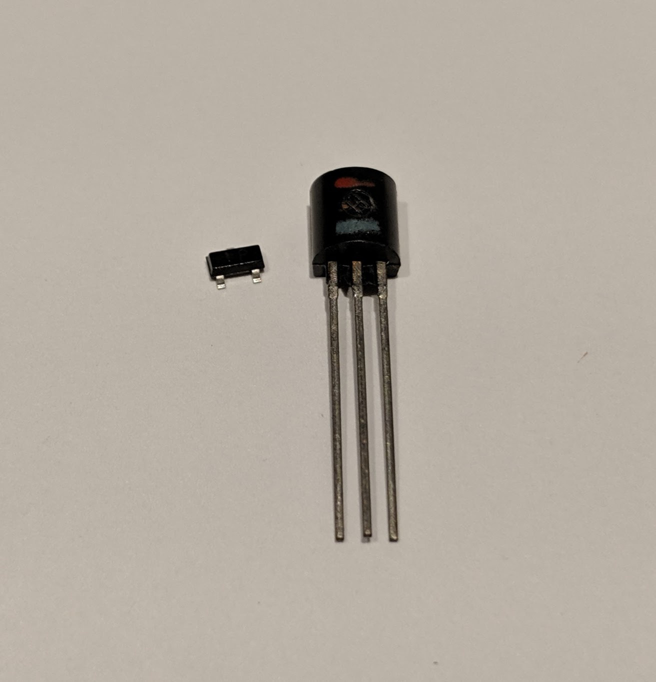
Now I'm soldering things down to 0402 SMDs (1/4 the size of the smallest component in the picture) using a needle point soldering tip and a microscope.
A pair of 2N2222 transistors, one SOT23 and one TO-92.
- Practice repairing broken traces
I got myself a T12 clone station recently. I've only had a junk iron that plugs into a wall socket and heats up to full blast whatever temperature with the big giant tip. Not very useful for more precise work.
I had this damaged Arduino Pro Micro clone sitting in my box of random stuff. At some point in time I had decided cut out out 4 pin headers for some reason. Damaged the corresponding traces in the process.
The repair worked! It was the MOSI, MISO, CLK, and RESET pins on the board. These pins can be used to have this board flash another Arduino board.
- Any advice for a beginner on how to best solder SK6812 MINI-E LEDs?
I am a beginner at soldering and am trying to assemble a number of these small pcbs. In the process, I have to solder SK6812 MINI-E LEDs and am struggeling to get that right. My problem is that the LEDs tabs are almost exactly as large as the solder pads on the PCBs and if I apply solder and flux to the pads and try to use hot air to settle the tabs into place, they tend not to stick to the pads and if I try to put them in "dry" and solder them with the soldering iron (like a through hole connection), I have trouble getting solder between the tab and the pads. Any advice? Any video that shows how to solder this kind of joint?
- So you've soldered your first MCU board - Fixing bad solder.
We often get asked what we think of beginners first soldering projects then offer suggestions how to improve their technique, and often, how to rescue their project.
In this video I've done my best to do a bad job of soldering header strips onto a QFP32 to DIP32 adapter board. There are some cold joints, some dry points, some blobs, a solder bridge, and some nice, corroded peaks.
How do you fix this so that it looks like you're experienced and know what you're doing?
Liquid flux to the rescue (and clean, good quality solder and a hot soldering iron and a good drag soldering technique.)
If you try this technique please come back here and tell us how it worked out.
Hakko FM-203 with FM-2027 handpiece and T15-D16 1.6mm chisel tip
MG Chemicals 4884-227G Sn63/Pb37 solder
Kester 186 liquid flux
- Why I love liquid flux.
I made a new video about why I love liquid flux and how much of a difference liquid flux can make to your soldering.
In this video I created a large blob of solder. I used the MG 4884-227G solder that I always use but once I had the solder down I cleaned away all of the flux then reheated the solder to cause it to oxidize. The now dry, oxidized solder is unruly and uncooperative. It blobs up and forms peaks and is just generally nasty.
Then, I bring some of my Kester 186 liquid flux to the party and the solder is reborn.
I just go to Ebay, type in Kester 186, and guy a bottle. 100ml of the stuff will last you for years unless you're doing a LOT of soldering.
- Is there anything in particular you want to see?
I've posted videos of myself soldering a SOIC8, a QFP32, and header strips. Is there anything else that anyone wants to see? Want to see me solder a QFP with a chisel tip instead of a GW tip? How I solder 0805 SMDs with a regular soldering iron? Want to see me reflow bad solder joints using a regular soldering iron and liquid flux?
Post your suggestions here and I will see what I can do...or maybe someone else will make a video or how to photo essay and post it to the community.
- Soldering header strips onto a QFP32 to DIP32 adapter board.
In this video I solder two 16-pin header strips onto a QFP32 to DIP32 adapter board.
Hakko FM-203 with FM-2027 handpiece and T15-BCM2 2 mm cupped beveled tip
MG Chemicals 4884-227G Sn63/Pb37 solder
Kester 186 liquid flux
- Hand soldering a 0.8mm QFP32 ATMEGA328PB
In this video I solder an ATMEGA328PB in a 32-pin QFP with 0.8mm pin pitch.
Hakko FM-203 with FM-2027 handpiece and T15-BCM2 2 mm cupped beveled tip
MG Chemicals 4884-227G Sn63/Pb37 solder
Kester 186 liquid flux
- Hand soldering a SOIC package with a 1.6 mm chisel tip in a regular soldering iron.
I few days ago in a comment here, or maybe in another community, I mentioned that I thought that soldering SOIC ICs was relatively straight forward to do with a regular soldering iron and a small chisel tip. I regularly solder SOICs and T/QFPs with nothing but a 1/6 mm chisel tip.
Obviously, it is much easier to do with a cupped beveled tip but it's within reach of most beginners with simple soldering irons.
In this video I solder a DS1307 real time clock in a SOIC-8 package to a SOIC-8 to DIP-8 adapter board.
- Fixed and upgraded Fender Blues Jr. guitar amp
I did this last week before finding this group, so no pictures of my soldering. I take it that the purpose is intended to be general electronics?
I bought a used tube amp for $400 (great price, I think), but it was noisy and smelled of smoke. I took it apart to wipe down the insides with isopropynol. I discovered the filter caps were leaking--no surprise really.
$50 of parts later, I replaced the larger capacitors and made a few tweaks to the tone stack. Sounds good for $450.
Maybe I'll post some more stuff later. I'm working on a custom mechanical keyboard with an interesting design. Still working out the kinks.
SAFETY NOTICE: don't open a tube amp without knowing what you're doing! Those big capacitors can carry enough voltage to kill.
- My soldering irons and tips.
When I first started soldering my parents bought me a (probably < $10 at the time) hobby soldering iron. That iron took a beating and was replaced with another hobby iron then another. I ended up with a hobby iron that I absolutely loved. It had a powder blue handle, a solid barrel (not rolled sheet) and was flared where the handle met the barrel. I used that iron for many years. I am not sure where it went. It may be in a box of tools somewhere or it may be gone for good.
I'm not sure exactly when I got my Weller WESD51 soldering station. It will have been between 15 and 20 years ago. At around $150 it was an expensive upgrade for me. That original station still sits on my desk and up until a few weeks ago was the only station on my desk.
[!image](https://i.imgur.com/km2HG2T.jpg)
I normally have an ETA (1.6 mm chisel) tip in the PES51. It meets most of my day-to-day soldering needs. I find that I can easily solder SMDs down to 0805, SOT23s, and SOICs with the ETA.
[!image](https://i.imgur.com/TMU94WW.jpg)
When I'm doing something like a QFP of TQFP I switch to a ETGW (2 mm beveled cup) tip. The ETGQ style Gullwing tip is the tip professionals use to hand solder chips with gullwing style pins.
Yes, this tip is a little bit oxidized.
[!image](https://i.imgur.com/zU41xTf.jpg)
I cleaned out the solder to show the cup in the photo. Immediately after I took this photo I fluxed and tinned the tip. It's all good and ready for the next time I use it.
[!image](https://i.imgur.com/wLpdJfV.jpg)
I have a range of other tips that I use from time to time when they are appropriate. They include (upper left to right then lower left to right):
ETAA - a 1.6 mm bevel
ETL - a long, heavy 2 mm chisel
ETR - a long, light 1.6 mm chisel
ETT - a 0.6 mm conical
ETU - a 0.4 mm bevel
ETX - a 0.2 mm bent conical
TETS - 0.4 mm long conical
The projects that I've been taking in recently (I don't call them jobs because I often do them for free) have been more complex. I've had to desolder SMD electrolytic capacitors and I've been soldering 0.4 mm pitch TQFPs. I needed a soldering station with a bit more range.
A few weeks ago my Hakko FM-203 arrived with the pair of FM-2027s you see in the cover photo. The green one is loaded with a T15-BCM2 which is a 2 mm beveled cup like the ETGW on the Weller and the yellow with a T15-D16 which is a 1.6 mm chisel like the ETA on the Weller.
I'm planning to add a FM-2022 tweezers at some point in the near future to help with those pesky SMD electrolytics.
- A broken pin on a 0.4mm TQFP.
This was an interesting repair. The little company that I work with discovered that one of the pins on the TQFP was not pulled out to the header on the breakout board. They needed that pin so they hired someone to desolder it, lift it, and solder a wire on the to cut the trace to one of the header pins and bring the wire out to it.
Unfortunately, the guy they hired to do the work messed it up pretty bad. You can soo the three pins to the right of this repair are damaged. He broke the pin that he was working on clean off the package. They gave it to me to try to save.
First, I rescued the damaged pins as best I could. Then I filed down the edge of the plastic package until I exposed the lead inside and soldered a 0.1 mm bodge wired onto it. I took that wire out to the pin on the header.
This is not an elegant repair but it got them back in business while they waited for a replacement BoB to arrive. I think they are still using this BoB for their development.
I do these fine repairs under an Olympus SZ40 microscope with a ring light.
[!image](https://i.imgur.com/JGDPq0D.jpg)
I always wanted an optical soldering microscope but could never justify the cost. I found this one in a microscope shop in Montreal for $200. For that price I couldn't not buy it.
- Can we talk about solderless breadboards? (More pictures in text.)
Most of the projects I design start out on solderless breadboards. The one in the bottom of this picture is a ROM switcher and reset circuit for a Commodore 64 that I'm working on. This circuit will fit inside the footprint of a 27256 ROM chip in a 2364 to 27256 ROM adapter.
Other projects are larger like this early prototype of my maple syrup machine room controller, the SapMaster...
[!image](https://i.imgur.com/WC0KFoM.jpg)
or this...something...that I was doing with an ESP32 and a Raspberry Pi Zero W.
[!image](https://i.imgur.com/WjrJmEB.jpg)
Over the years I've collected a number of solderless breadboards. Some I bought myself and others came with kits that I bought. A number of them came from Hacker Boxes when I had a subscription before the pandemic. I had the delivered to a UPS store in Ogdensburg, NY and drove over and picked them up once a month. Hacker Boxes are cool. Definitely check them out.
Some of the solderless breadboards in my BREADBOARD drawer were cheap, Chinese knock-off breadboards. They had...issues...
[!image](https://i.imgur.com/C3DkIhU.jpg)
not to mention the fact that the contacts were SUPER cheap. They often didn't line up well with the holes and prevented pins from being plugged in. Dupont wires and header strips were a BIG challenge and when plugging in a header strip the contacts often stretched and didn't spring back properly.
I finally decided that it was time to replace all my cheap breadboards with better ones.
The cheap ones can be bought on AliExpress for CAD$2. The better ones cost in the neighborhood of CAD$10. I spent some time doing research and talking to friends in the electronics business and settled on Global Specialties (pictured above.) Just about any of the brands available from Digikey or Mouser will be the same quality.
The contacts are nickel plated phosphor bronze and are rated for 1.5A at 36V.
I've switched my prototypes over to the new breadboards and am very happy with how the feel.
- PIC18F97J94 0.5 mm TQFP
A pair of friends, brothers, own a small business manufacturing custom PCBs and systems. The older of the two has always done all of the hardware and the younger the software. The older brother had a heart attack several years ago and has had a shake and weakness in his right hand ever since. He can no longer solder small components so I have taken over that function for him. I love soldering and I love the challenge.
This is a PIC microcontroller that I soldered onto a breakout board for them. It's a 0.5mm pitch (0.5 mm from the center of one pin to the center of another pin) TQFP package. I used a Weller WESD51 soldering station with a PES51 soldering pen and an ETGW angled, cupped soldering tip.
[!image](https://i.imgur.com/wWOJSPV.jpg)
I do all of my fine soldering under an Olympus SZ40 binocular microscope that I bought for $200 a couple of years ago from a microscope shop in Montreal.
[!image](https://i.imgur.com/vq3rnFx.jpg)
- HOW TO: Hardware debounced tact switch for solderless breadboards.
Yesterday I posted a picture of a little tact switch that I installed on a piece of protoboard with a hardware debounce circuit on the bottom. I love those little things and thought I would share a how to for making them.
The first thing you need is the little piece of PCB. I had a bunch of these Altoids Tin protoboards made up a few years ago.
I break them down into smaller pieces,
then I break those down to the size that I need,
then I sand the edges to make them pretty (and also to make them small enough to sit beside each other if I need more than one.
Note that the board consists of four columns of 3 connected pads and four columns of 2 connected pins.
Next, I assemble (almost) all of the components that I'm going to need. These are (top to bottom, left to right) 1 uF 0804 capacitors, 1 K 0804 resistors, and 10 K 0804 resistors, the little sanded piece of PCB, three r-pin pieces of header strip (I like to use one red, one blue, and one black but you can use all black or any other color you want), and a 5 mm x 5 mm tact switch (I like the ones with the 7 mm shaft as shown because I can put a cap on them but any old tact switch will do.) Missing from this picture is a
First, we're going to install the debounce components on the bottom of the board. With the columns of 2 at the top and the columns of 3 at the bottom you're going to bridge the gap on the second column with the little jumper wire and the third column with the 10 K resistor. Next you're going to bridge the top end (at the 2-pin column side) of the little wire and the 10 K resistor with the 1 uF capacitor. Finally, you're going to bridge the bottom of the right two 2-pin columns from the pint where the 1 uF capacitor and 10 K resistor meet to the bottom of the last column leaving the hole unobstructed. It will look like this:
The next part is tricky. You have to push some of the pins on the header strips through. On the black one and the red one (or two of the black ones) you're going to push three of the pins through from the long side. On the blue one you're going to push through one of the pins from the long side as shown.
Now, push the header strips into a breadboard as shown. The pins that you pushed through do not go into the breadboard, they stick up into the air. It's important that the pins that you didn't push through on the red and black strips line up with the one that you did push through on the blue strip as shown.
Next, put the PCB over the pins as shown. The soldered components should be on the bottom of the board facing the breadboard. Make sure that the point where the capacitor and two resistors meet is in line with the three special pins on the header strips. If thy don't you can turn all of the header strips around and try again.
Next, clip the pins you pushed through, the ones stick up into the air, off flush with the PCB.
Now, push the ends of the short pins you didn't push through and cut off down flush with the surface of the PCB.
Check one more time that the three special pins and the point where the three components meet are lined up then solder the pins marked with an X.
Now, grab your tact switch. Note that the legs have bumps in them to help hold them in the holes while you solder them.
Use a pair of smooth jawed plyers to squeeze the legs straight then bend two pins out at 90 degree angles as shown.
Trim off the ends of the pins you bent.
Insert the tack switch into the PCB as shown. The bent pins will be over the two pins in the blue row that you didn't solder above. You will need to bend the bent pins out a bit to make them reach the middle of the pads.
Now, solder all four pins pushing down on the body of the switch to make sure it's tight to the PCB and lined up square to the board.
Once you've soldered the switch in place flip it over and make sure that there is a good connection between the end of the 1 K resistor and the pin of the switch. Add a bit of solder if you need to.
Now you can plug the switch into your breadboard and add a Dupont wire or jumper wire to the pin of your MCU.
Note that the red header strip and blue header strip match up with the red and blue rails on the breadboard. This switch can only be installed on this side of the breadboard to get a debounced going low switch. The construction of a switch for the other side of the breadboard is exactly the same but you switch the position of the red and blue header strips.
This is what one of these little switches looks like in a project. This is a prototype for a ROM switching and RESET circuit I'm going to build into a 23xx to 27256 ROM adapter for the Commodore 64.
- Debounced Breadboard Switches
This is a cool little project. I often prototype circuits on solderless breadboards. I've mostly switched to using 0805 SMD resistors and capacitors. I have a box of 1/4W 1% and a box of 1/2W 1% THT resistors but they aren't neat when they're plugged into the breadboard. I've got 0.1uF capacitors but no 1.0uF in THT.
I decided to make up these little tact switches ready to plug into the breadboard with built in hardware debounce. The debounce circuit also provides a pull-up resistor.
Each switch has a 10K 0805 resistor between Vcc and the MCU pin, a 1.0uF 0805 capacitor between GND and the MCU pin, and a 1K resistor between the switch and the MCU pin. The end result is a nicely debounced going low switch with a built in pull-up. They work great and I can just grab one when I need one and plug it in. I've made versions that will plug into one side or the other of the breadboard so that I can have a switch on either side depending on what works best.
The row with 3 pins is GND and the adjacent row with 1 pin is Vcc. The single pin at the other end is the debounced switched output to the MCU pin.
If anyone's interested I can post pictures of the process of making these and how I wire them up so that the work correctly.
- A repair that I did for a local gentleman recently.
I have an ad up on Kijiji saying that I will do electronic repairs. A local gentleman contacted me and said that he had an air hockey table that he had bought that had a broken connector on the controller board. I said I would take a look. I visited him and found that he was in his 80's.
When I opened the controller this is what I found.
I assumed that he probably had the table for his kids or more likely grandkids to play when they visited.
Some super glue, a bunch of scraping, some small pieces of wire, and some careful soldering later and he's back in business.
It turns out that he and his wife play air hockey from time to time.
- Soldering Tools and Materials from Beginner to Advanced (Part 3)
#Soldering Tools
Most soldering iron manufacturers make some sort of soldering tools or soldering aids. They are an assortment of little pokers and hooks and forks and pry tools. I've looked at them from time to time but all I've ever used are the little plastic things that come with Weller consumer soldering irons.
I love these things. They used to have a fork on one end but I find the poker MUCH more useful so I just sanded a blunt one on one end and sharpened the one on the other end. I always have one near and often in my left hand when I'm soldering. I use them to position small components and hold them while I'm soldering them. I push and pry and poke things with them. I like them so much that I reached out to Weller about buying more. They don't sell them individually but sent me a few in the mail. Awesome customer support!
#Scalpel
The only other thing that I can think of that's part of my tools and materials is a pair of scalpel handles and blades.
This is a No. 3 handle with a No. 11 blade and a No. 4 handle with a No. 22 blade. I use these for all kinds of cutting and scraping operations. I use them for placing stickers and cutting header strips. They are an invaluable tool. You can buy plastic scalpel handles for $1. These stainless steel surgical handles are less than $10 each. The blades you can buy expired in boxes of 50 or 100 for a very reasonable price. You can even cut thin copper wire with these blades.
I think that's everything for now. I might think of something else later and come back and add it. I'll pin this post to the community.
Comments, additions, and questions are welcome.
I remembered another thing!
#Pinchy Things
I have a drawer labelled "TOOLS" and a drawer labelled "PLIERS". Anything scissor like goes in the PLIERS drawer.
In this picture from left to right are:
Flush cutting pliers. They're like side cutters or diagonal cutters but they are ground on one side only so you can cut really, REALLY close to the board. The blades are normally fairly soft so you can only cut soft things like copper wires and component leads. You can buy REALLY expensive ones but these are cheap, house brand ones that I buy at Princess Auto three or four at a time. Seriously, I have like 12 pairs. There are 3 pairs in my PLIERS drawer right now. Next are cabling scissors. They look like hell but they are amazing. One blade is serrated so that wires don't slip out as you cut them. They're tough as well and can cut through anything short of a nail (though they will cut through some small nails.) Next is a pair of little scissors that I use for cutting labels and things of that type. Tweezers are important for handling small components. I have a stainless steel pair, a squeeze open stainless steel pair, and a ESD safe coated stainless steel pair. The squeeze open ones are awesome because you squeeze them open and the spring closed. You can use them to hold wires or small components while you solder them. Far right is a small pair of cheap side cutters. I use those for anything I don't want to use my flush cutters for. Their blades are hardened better than the flush cutters so they don't damage as easily.
- Soldering Tools and Materials from Beginner to Advanced (Part 2)
#Isopropyl Alcohol
If you're soldering you need isopropyl alcohol (or another alcohol. I have methyl, ethyl, and isopropyl in wash bottles under my desk all the time. Be forewarned that if you're using methyl the molecule is small enough to move through your skin easily and it's toxic so be cautious.) I have a wash bottle under my desk. I keep a little pill bottle full of isopropyl alcohol on my desk that I drop little boards in when I build them and shake to clean. You'll also need a little brush but I'll cover that next.
You need to clean the flux off your solder joints because your boards look nasty if you don't and the flux can corrode the traces on the board and the pins on your components.
#Brushes
I use a simple acid brush that you can buy individually or in bags of 10 at any hardware store for a couple of dollars.
I drill a small hole through the ferrule and put an M3 machine screw through with washers on either side to hold the bristles in place. I then cut the bristles down so that they are shorter and stiffer.
When I'm cleaning I add isopropyl alcohol, scrub with the acid brush, then rinse with clean isopropyl alcohol.
#KimWipes
This is one that I've had around for years but didn't think to use when soldering. They are a laboratory wipe and they are lint free. I use them with isopropyl alcohol to wipe anything I don't want to leave a bunch of lint on. They're relatively expensive but if you only use them for cleaning with alcohol a box will likely last you for years. You can buy KimWipes on Amazon by the box.
#Polyamide/Kapton Tape
This stuff is AWESOME! If you've taken apart old electronics of seen inside a spacecraft you've likely seen kapton tape. It's the same color as old amber beer bottles. The nice thing about it is that it's tolerant of extremely high temperatures. You can tape things down that you're soldering and it won't melt unless you heat it directly. It's good from -269°C (-452°F) up to 400°C (752°F). The stuff is magic.
#Solder Removal - Solder Wick
When you're soldering things you're eventually going to want to desolder something. The first thing most people use is solder wick. It's a braid of fine copper wires coated in flux. You place the solder wick on the solder joint, heat is up, the solder melts, and wicks into the solder wick. With practice you can get good at removing components with solder wick.
You will move on from solder wick, though, to a solder sucker at some point. Keep the solder wick. I use it after I've removed components with the solder sucker to really clean up the pads in preparation for resoldering.
#Solder Removal - Solder Sucker
The venerable solder sucker. It's a spring loaded monstrosity that does a decent job in certain circumstances. When you only have access to one side of the board you have to heat the joint, remove the soldering iron, place the solder sucker, and press the button before the solder melts hoping that you remembered to push down the plunger. They can be frustrating to use. When you have access to both sides of the board you can heat from one side and suck from the other. With practice you can suck the solder out of a join so completely that the component lead just pulls or falls out of the hole.
#Tip Cleaner/Tip Tinner
Maintenance of your soldering iron tip is essential. A clean, well tinned tip makes everything about soldering easier. In fact, in aerospace soldering you clean the solder wire and cut a short piece, clean the joint to be soldered, and clean and tin your tip before soldering each joint. I ordered a copper scrubber style tip cleaner off AliExpress. Just between us, I ordered 4 because they were cheap. I modified mine by adding a disk of thick steel to the inside of the base and a silicone rubber disk to the outside so that it doesn't move around. I quickly stick my tip in every two or three joints then get right back into the soldering. When I'm ready to put my iron away at the end of the session I jab it in three or four times moving it around to really clean off the tip then I heavily tin the tip, shake off the excess, and hang up my iron in the holder.
The tip tinner is a mixture of solder powder and aggressive flux. You turn your iron up high, melt it into the cleaner, then stir it around a bit. It really cleans up and tins your tip.
- Soldering Tools and Materials from Beginner to Advanced (Part 1)
In this post I'm going to try to pull together some photos, some comments, and some advice from my more than 40 years of hobby soldering.
The most important advice that I can give you is to buy the best tools and materials that you can afford. You don't need to start with a $1,000 soldering station but buy the best iron you can afford. I strongly recommend buying a basic pencil iron from a well known brand for your first iron.
#Soldering Iron
You can buy a Weller for USD$30 or Hakko for USD$50. Either of those irons is a great place to start. If you can't afford one of those then get what you can afford. The iron isn't as important as other things that I'm going to talk about.
#Solder
The next thing to consider is solder. Buy good solder. Most good solders you can buy in small, affordable quantities. I buy solder in 125g (1/4 lb), 250g (1/2 lb), and 500g (1 lb) rolls and they last a LONG time. If you're not doing a lot of solder you can buy a tube and it will do you for a good, long while. Again, I recommend buying a good brand name solder. I use MG and Kester and Multicore. They are all great solders. You want to get a rosin or flux core solder.
Here's a picture of the solders that I have on my desk right now.
They are (from upper left clockwise):
FSH 6045 CKF
This one is actually a silver brazing solder. It's 45% silver and used when you really, REALLY want things to stay stuck together.
MG 4900-112G 0.032" (0.81mm) Sn96.2/Ag2.8/Cu0.4
This is a strong, lead free silver containing solder that I use for important repairs where I want a strong, lead free joint.
Kester 24-6040-0053 0.050" (1.27mm) Sn60/Pb40
This is a medium weight tin/lead solder. I use this one for heavier through hole components and heavier wires.
Multicore 370 Flux 0.064" (1.63mm) Sn63/Pb37
This is the heaviest solder that I keep on my desk. This is another tin/lead solder and I use it for heavy filling and heavy wires. If I'm going to solder a power cable or a wire on my trailer this is the one I use.
Kester 24-6337-0001 0.10" (0.25mm) Sn63/Pb37
This is the other end of the solder spectrum. This tin/lead solder is the lightest solder that own. It's extremely fine and I use it for soldering the smallest of surface mount components. I use this when I'm using a needle tip on my PES51 pencil iron to solder an 0402 surface mount resistor.
Kester EP256 Sn63/Pb37
This one is a tin/lead paste solder. I've used it a couple of times but all of the soldering that I do on a regular basis is done with an iron and wire solder so this is more of a novelty on my desk in case I ever need it.
MG 4884-227G 0.025" (0.64mm) Sn63/Pb37
This one is my go-to solder for just about everything. It's a tin/lead solder that's small enough for small surface mount components but big enough for larger through hole components as well. When I reach for solder 99.5% of the time it's this one that I'm reaching for.
#Flux
Buy liquid flux.
Seriously. It's life changing. I bought liquid flux for the first time a few years ago after soldering for more than three decades and I can't believe that I struggled for as long as I did without it. You know how when you reheat a joint the solder gets all rough and you get peaks and points that you can never get to go away? A drop of liquid flux on the joint and it's beautiful, smooth, and shiny.
Did I mention that you should buy liquid flux?
I use Kester 186 liquid flux. You can buy it in little squeeze bottles on Ebay. Flood your work with liquid flux. I literally cover what I'm working on in liquid flux. It's a bigger-hammer solution but it makes life so much easier.
Seriously, go to Ebay right now and buy some liquid flux.
- Intro Post - MapleEngineer
Hello.
I'm MapleEngineer. I'm from Eastern Ontario and I've been soldering for over 40 years as a hobbyist. My user name is MapleEngineer because I'm an artisan maple syrup maker and design and build my own machinery and industrial controllers.
I, like just about everyone, started out with a pencil iron and a bit of solder in a clear plastic tube.
If you're into electronics and soldering please subscribe and feel free to contribute and ask questions.